ShapeFinity Help & Tutorial
ShapeFinity designs 3D-printable organizer trays that fill a drawer. This tutorial walks through a whole project, from measuring the drawer to printing the files. Work through the tabs at the top of the app from left to right: Drawer → 2D Layout → 3D Layout → Tray Designer → Dividers → Splicing.
Quick start
- Try the exampleClick Load Example (top right) to see a finished drawer using most features: L and T shapes, floor patterns, a stack, finger scoops, label tabs, finger notches, removable dividers with a box insert, an obstruction and spliced trays. Ctrl+Z brings your own layout back.
- Measure your drawerOn the Drawer tab, enter its inside width, depth and height, or pick a preset.
- Add traysOn 2D Layout, click a tray in the ADD bar, then drag it into place. It snaps to walls and other trays.
- Size themClick a tray and type exact sizes in the right panel, or use Fit to space to grow it to its neighbors.
- DesignDouble-click a tray to open the Tray Designer: walls, floor holes, ribs, nesting. Deep drawer? Add tray on top to stack more trays on it. Add Dividers if you want compartments.
- PrintIf a tray is bigger than your printer, Splicing cuts it into pieces. Then download STL or STEP at the top left.
Your work is saved automatically in this browser as you go. To keep a copy, move it to another computer, or start over safely, use Project › Save to download a layout file.
1 Set up the drawer
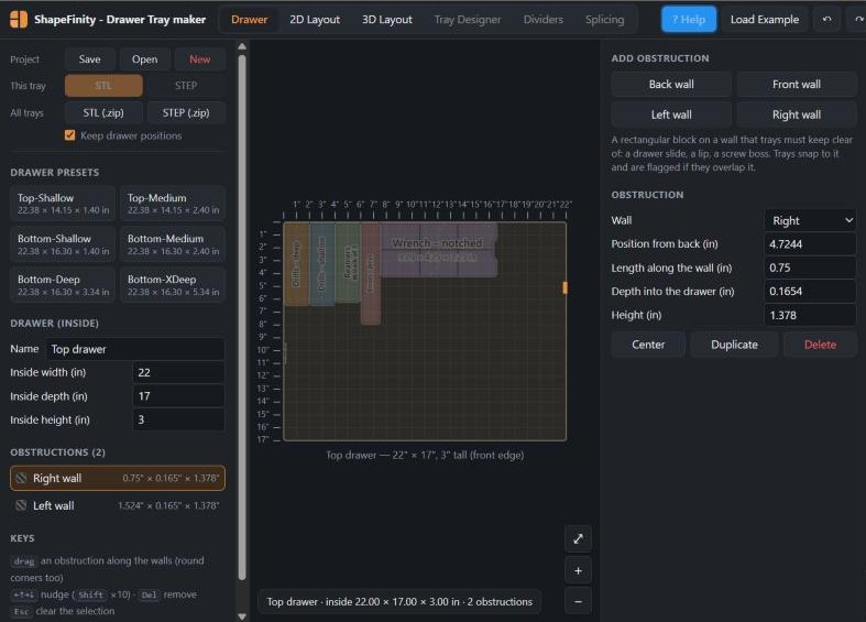
- Choose mm or inch in the box at the top right. You can switch any time; everything is converted.
- Click the Drawer tab. Pick one of the Drawer presets, or type your drawer's inside width (left to right), depth (front to back) and height, and give it a name.
- Measure the inside of the drawer at its narrowest point, and the height from the drawer floor to the bottom of whatever is above it when it closes.
- Obstructions: if something sticks into the drawer (a drawer slide, a lip, a screw head), click Back / Front / Left / Right wall on the right to add a block there, then drag it along the wall and set its size. Trays will snap against it and are flagged if they overlap it.
Measure twice. A tray that is 1 mm too big won't fit, and the clearance gap (next step) is your safety margin.
2 Lay out the trays
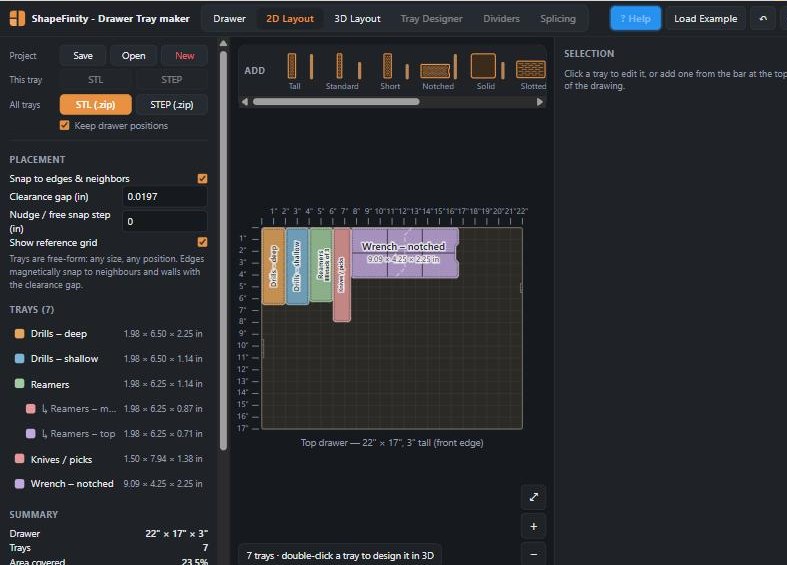
- Click the 2D Layout tab. The drawer is drawn from above, with a ruler on two edges; the front of the drawer is at the bottom.
- Click a tray in the ADD bar to drop it in: Tall, Standard and Short (heights from real trays), Notched, Solid floor, Slotted, 2×2 compartments, and L, T and uneven T shapes. Scroll the bar for more.
- Drag a tray to move it. With Snap to edges & neighbors on (left panel), edges jump into line with walls and other trays, leaving the Clearance gap between them so trays drop in easily (0.5 mm ≈ 0.02″ works well).
- Use the arrow keys to nudge the selected tray (Shift for ×10), R to rotate it, Ctrl+D to duplicate, Del to delete.
- Zoom with the mouse wheel or the + / − buttons; drag empty space (or the middle mouse button) to pan; ⤢ fits the whole drawer.
Watch the Summary at the bottom left: area covered, free area, and Problems. "none" in green means every tray fits.
3 Size and shape a tray
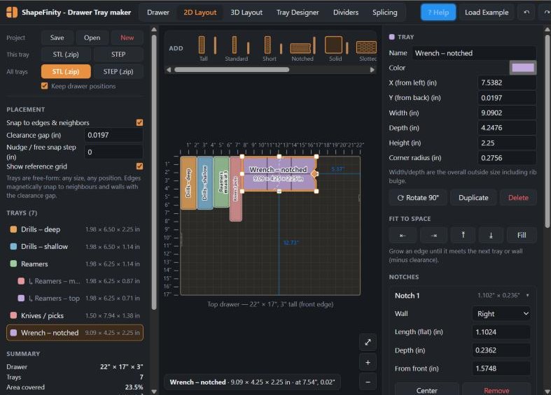
Click a tray (in the drawing or the tray list) to select it. The right panel shows:
- Name and color: the name is used on the file names and in the 3D view.
- Position (from the left and back walls) and size: width, depth, height and corner radius. Width and depth are the overall outside size, including the bulge of the grip ribs. Or drag the square handles in the drawing.
- Rotate 90°, Duplicate, Delete.
- Fit to space: the arrow buttons grow one edge until it meets the next tray or wall (less the clearance gap); Fill grows all four.
- Notches: a 45°-sided cut into one wall, to clear an obstruction. Choose the wall, the flat length, the depth and the distance from the front, or drag the ◆ in the drawing. The opening at the wall is length + 2 × depth.
- Edit as custom shape…: turns the outline into points you can drag. Click a + on an edge to add a point; select a point and press Del to remove it. Back to rectangle undoes it.
The Stack section lists the trays stacked on this one and has + Add tray on top (see step 6). The 3D features list at the bottom summarizes the tray's ribs, nesting, floor holes, dividers and splices, with a shortcut to the Tray Designer.
4 Check the whole drawer in 3D
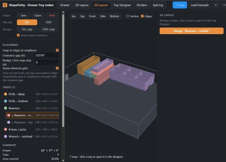
The 3D Layout tab shows every tray in place inside the drawer. Drag to orbit, scroll to zoom, right-drag to pan, or use the Iso / Top / Front / Side / Bottom buttons. Section cuts the view open so you can see wall and floor thicknesses; Edges outlines the shapes.
Stacked trays are shown at their real height. The selected tray is lit up with orange edges. Click a tray (or Design "…" on the right) to open it in the Tray Designer.
5 Design the tray
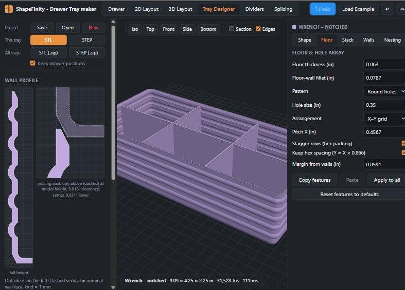
Double-click a tray (or open the Tray Designer tab with a tray selected). The right panel shows one section at a time; pick it with the tabs at the top (the app remembers the last one). The model updates as you type:
- Shape (Size & shape): overall width, depth, height, outer and inside corner radii.
- Floor (Floor & hole array): floor thickness, the fillet where floor meets wall, and the hole pattern (solid, round, hex, square, diamond or slots), hole size, spacing, staggered rows, and the margin kept clear of the walls. Honeycomb (even web) keeps the same amount of plastic between every pair of holes.
- Walls (Walls & stiffening ribs): wall thickness, and horizontal ribs (round or 45° V) that stiffen the walls and make the tray easy to grip: depth, spacing, how far below the rim the first one sits, and the lowest height for ribs.
- Nesting (nesting profiles): a chamfered foot under the tray and a lead-in lip on the rim, so a stacked tray nests into the one below. Fit clearance makes the stack looser or tighter.
- Extras:
- Finger scoops: a big rounded ramp where the floor meets the walls on one side (front by default) of every compartment, so small parts slide out instead of hiding in the corner. Scoop radius sets how far it reaches; it is smaller in shallow compartments. It runs on into the rounded corners of the tray. Floor holes keep clear of it.
- Label tabs: a shelf under the rim on one side of every compartment, to stick or write a label on. Its underside is at 45°, so it prints without supports. A full-width tab runs right into the rounded corners of the tray. Set its depth, its length (0 runs the full width of the compartment, or give a length and align it) and how far below the rim it sits.
- Finger notches: U-shaped dips in the rim, to get a finger under what is inside or to lift the tray out. + Add finger notch, pick the wall and its position along it; width, depth and rim rounding apply to all of a tray's notches. A divider (or removable plate) that meets the wall inside a notch gets the same dip, so it doesn't stand up in the gap. They show as short orange bars on the tray's outline in the 2D Layout.
- Stack: the trays stacked on this one, and + Add tray on top (see step 6).
The Wall profile on the left draws the wall's cross-section (outside on the left) and, dashed, the tray stacked on top. The Model box shows ribs, number of floor holes, how deep a stacked tray seats, volume, an estimated PLA weight, triangle count and Watertight ✓. Copy features / Paste / Apply to all reuse one tray's settings on others; Reset features goes back to the defaults.
6 Stack trays in a deep drawer
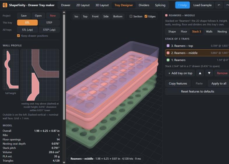
A deep drawer can hold several trays stacked on top of each other. Each one is a real tray you print: it has its own height, walls, floor, nesting profile, dividers and splices, but it keeps the 2D shape and place of the tray at the bottom of the stack (the base).
- Select a tray and click + Add tray on top in the Stack section (2D Layout right panel, or the Stack tab in the Tray Designer). The new tray is a copy of the top one; change its height and features as you like. Add as many as the drawer has room for.
- The Stack section lists the trays from top to bottom with each one's height and the height it sits at, and shows the stack's total height against the drawer. Click a tray in it to select it.
- ▲ / ▼ move the selected tray up or down. Any tray can go to the bottom: the one at the bottom becomes the base. Remove takes one tray out (removing the base makes the next one up the base).
- Each tray sits on the one below at its nesting seat: the foot chamfer of the upper tray drops into the rim lead-in of the lower one (1.92 mm with the default profiles). With either chamfer turned off, the upper tray sits on the rim.
In the 2D Layout only the base is drawn, labeled stack of N; the stacked trays are listed indented (↳) under it in the tray list. Select the base to move, resize, rotate or reshape the stack. Dragging a stacked tray moves the whole stack, and rotating turns each tray's own dividers and splices with it. Del on the base removes the whole stack. In the Tray Designer the rest of the stack is drawn faint above and below the selected tray; click one to select it.
Problems for stacks: stack taller than drawer, and dividers hit the tray above (the dividers must stop below the foot of the tray stacked on them). A stacked tray only counts as hitting an obstruction if the obstruction reaches up to its height.
7 Add dividers
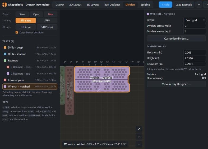
- With a tray selected, open Dividers. For equal compartments, leave Layout on Even grid and set how many dividers go across the width and across the depth.
- For your own layout, click Customize dividers… (it starts from the current grid). Then click a compartment to split it front-to-back or left-to-right, or to put a box (four walls) inside it.
- Click a divider section to select it: drag to move it (it snaps into line with others), Del removes that section, Shift+Del the whole line. A red dot marks a loose end; Extend (or double-click its handle) runs it to the next divider or wall.
- Removable (print separately) makes each divider a plate you print on its own. It slides into a slot of two rails on the tray wall, and where two plates cross they half-lap (one slotted from the top, the other from the bottom). At a T-joint the plate that runs through gets a slot from the top, and the upper half of the plate that ends there drops into it as a tongue, so it is held on both sides. At a square L-corner the two plates half-lap over each other. With an L-corner radius (custom layouts) the rounded corner stays, and plates joined by rounded corners print as one piece: a box with four rounded corners becomes a single insert. Straight plates export lying flat; a piece with rounded corners exports standing up, as it sits in the tray. Rails and divider ends reach into the grooves between stiffening ribs, so there are no gaps behind them. Slot clearance per side sets how loose they fit (0.2–0.3 mm suits most printers). In the 2D Layout removable dividers are dashed; in 3D the plates are grey.
- Under Divider walls, set their thickness and their Height (from the bottom of the tray). Below rim is the same setting measured down from the rim; when the tray height changes, the dividers keep their distance below the rim. If a tray is stacked on this one, a note says how far it sinks in and warns when the dividers would hit it.
Floor holes automatically keep clear of the dividers.
8 Split big trays to fit your printer
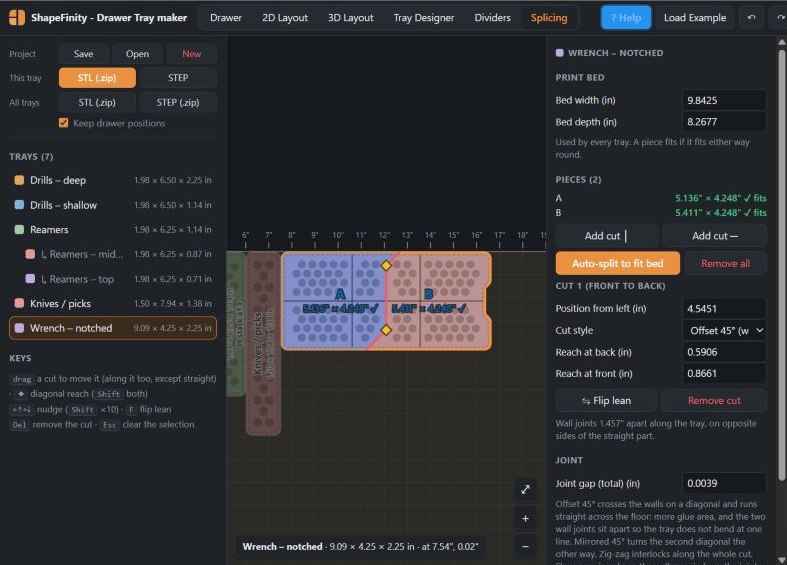
- Open Splicing and enter your printer's bed width and depth (used for every tray). The Size line says whether the whole tray fits (a piece fits either way round).
- Click Auto-split to fit bed for the fewest pieces that fit, or Add cut │ / Add cut ─ to place cuts yourself. Click a cut to select it. F flips its lean; Del removes it.
- Choose the joint style for the selected cut (all four are described below the steps).
- For the 45° styles, Reach at back / front (or left / right) set each diagonal separately; drag a yellow ◆ to change one (Shift changes both).
- Drag a cut to move it across the tray. Offset, mirrored and zig-zag cuts also move along their length: the 45° joints slide along the tray, and zig-zag teeth slide along the cut. The arrow keys do the same. The joint gap leaves room for glue.
- Offset 45° (default): diagonals across both walls, leaning opposite ways, with a straight run across the floor. More glue area, and the two wall joints sit apart so the tray doesn't bend at one line.
- Mirrored 45°: the second diagonal mirrors the first, so both wall joints sit on the same side of the straight part.
- Zig-zag 45°: interlocking teeth all the way across. Tooth size sets their depth, Angle turns the cut up to ±45°, and Tooth shift slides the teeth along it.
- Straight: a plain cut, which can be turned up to ±60° with Angle.
Glue the pieces with CA (super glue) or a plastic cement suited to your filament; the 45° joints give a lot of surface.
A cut must run wall to wall. If an angle or reach is so big that it leaves through a side wall, the tray is flagged splice: a cut runs off the side of the tray.
9 Save and export
The buttons at the top of the left panel are the same on every tab:
| Button | What you get | Use it for |
|---|---|---|
| Project › Save | <drawer name>_layout.json | Backing up your design or moving it to another computer. |
| Project › Open | loads a saved layout file | Continuing a saved project. |
| Project › New | an empty drawer (your old layout stays in undo) | Starting fresh. |
| This tray › STL | one STL file (a .zip of one STL per piece if spliced). With removable dividers, a .zip with the tray and …_dividers.stl: the plates in place in the tray with Keep drawer positions on, otherwise laid flat for printing | Printing the selected tray in any slicer. |
| This tray › STEP | an exact CAD solid (each splice piece its own solid; removable divider plates as solids of their own beside it) | Editing in Fusion, Onshape, FreeCAD, etc. |
| All trays › STL (.zip) / STEP (.zip) | every tray (stacked ones included) and layout.json; with Keep drawer positions on, also the drawer (floor, walls and obstructions) as a reference | Printing or checking the whole drawer at once. |
| Keep drawer positions (on by default) | every export keeps the tray where it sits in the drawer, stacked trays at their height. Origin: the drawer's front-left inside corner on its floor; X right, Y toward the back, Z up. Off: each tray is centered on the origin. | Importing trays into CAD in the right place relative to each other; slicers rearrange parts anyway. |
The first STEP export loads a 14 MB CAD engine, so it can take a little while; later exports are quick.
Slicers (PrusaSlicer, Bambu Studio, Orca, Cura) merge the dividers into the tray automatically. Print open side up, no supports needed.
Keyboard and mouse shortcuts
| Where | Shortcut | Action |
|---|---|---|
| Everywhere | Ctrl+Z / Ctrl+Y (or Ctrl+Shift+Z) | Undo / redo |
| 2D Layout | drag · double-click | Move a tray (a stacked tray moves its whole stack) · open it in the Tray Designer |
| 2D Layout | ←↑→↓ (Shift ×10) | Nudge the selected tray |
| 2D Layout | R · Ctrl+D · Del · Esc | Rotate · duplicate · delete · deselect (or leave shape editing) |
| 2D views | wheel · drag empty space / middle button | Zoom · pan |
| Drawer | drag · arrows · Del · Esc | Move an obstruction along the walls · nudge · remove · deselect |
| Dividers | click · drag · Del · Shift+Del | Select a compartment or section · move a section · remove it · remove its whole line |
| Splicing | drag · ◆ · F · Del | Move a cut (across, or along it for offset, mirrored and zig-zag cuts) · change a diagonal's reach (Shift both ends) · flip its lean · remove it |
| Splicing | ←↑→↓ (Shift ×10) | Nudge the selected cut across, or slide it along (not straight cuts) |
| 3D views | drag · right-drag · wheel | Orbit · pan · zoom |
| Tray Designer | click a faint tray | Select that tray of the stack |
Troubleshooting
| What you see | Why, and what to do |
|---|---|
| Tray Designer, Dividers and Splicing are greyed out | They work on one tray: select a tray first. |
| A tray is marked as a problem | The Summary and the tray's panel say why: outside drawer, overlaps …, hits an obstruction, taller than drawer, stack taller than drawer, dividers hit the tray above, bigger than the print bed (splice it), a spliced piece is bigger than the print bed, or a splice: problem with a cut. Fix it until Problems says "none". |
| Trays won't line up exactly | Turn Snap to edges & neighbors on, or type exact X/Y values. Set Nudge / free snap step for fixed steps. |
| Stacked trays are too tight or too loose | Change Fit clearance per face on the Tray Designer's Nesting tab, and print a short test tray first. |
| Removable dividers are too tight or too loose | Change Slot clearance per side under Divider walls, and print one plate to test first. |
| Dividers stop trays nesting | Lower the divider Height (or increase Below rim) under Divider walls so the dividers end below the nesting seat. |
| I can't resize a stacked tray | A stacked tray takes its shape and place from the base. Select the base (bottom of the stack) to move, resize or reshape the whole stack. |
| My layout disappeared | Layouts are saved in this browser on this computer only. If you loaded the example or started new, press Ctrl+Z. Use Project › Save to keep a file. |
| Want to know how the shapes are made? | See How it works: the wall profile, ribs, nesting math, hole patterns and the 3D mesh. |